A specialist website by Oxford Industrial Automation

UK machine vision & robot integration · 01865 416830

Non-contact automated measurement

Machine vision dimensional inspection systems

Measure visible edges, gaps, diameters, positions, angles and profiles during production. We engineer the optics, calibration, presentation, software and line response around the tolerance that actually matters.

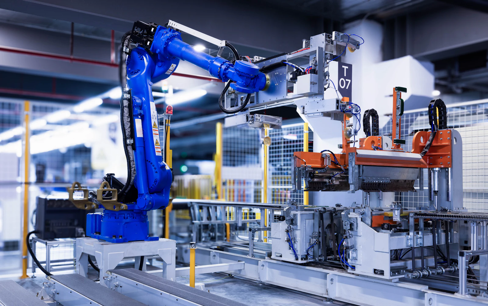
A blue industrial robot arm beside a production fixture.
MeasureEdges, gaps, diameters, angles, positions and profiles
ControlOptics, calibration, lighting and product geometry
ActPass, reject, grade, record or feed back to the process

Direct answer

What is machine vision dimensional inspection?

It is non-contact measurement from calibrated images. A system locates defined product features, converts image coordinates into engineering units and compares the result with specified limits. The useful output includes the measurement, decision, traceable record and production action.

01 / Measurement design

Start with uncertainty, not pixel count.

The required tolerance, field of view and product geometry determine whether 2D imaging, silhouette measurement, multiple views or 3D profiling is appropriate. Resolution alone does not establish accuracy.

  • Define the feature, datum, nominal value and decision limits
  • Allocate an uncertainty budget across optics, calibration and mechanics
  • Control height, tilt, focus, motion and vibration
  • Use calibrated reference artefacts and a documented verification method
02 / Production integration

Turn the result into a controlled process decision.

Measurement can create a pass/fail result, grade a product, guide assembly, update a process setting or produce a traceable value. The physical response and record are designed with the image measurement.

  • Edge, gap, hole, diameter, angle and position measurement
  • Silhouette, profile and feature-to-feature checks
  • Recipe-controlled tolerances for different formats
  • Result transfer to PLC, HMI or production data systems

Measurement chain

Keep every source of variation under control.

The result is only as dependable as the image, calibration, feature definition and product presentation behind it.

01

Define

Agree datums, dimensions, limits and decision rules.

02

Calibrate

Relate image coordinates to a controlled reference.

03

Measure

Locate the feature and calculate the required value.

04

Verify

Challenge repeatability across samples, shifts and formats.

Measurement opportunities

Automated gauging for visible product geometry.

A feasibility review confirms whether the required feature and tolerance are suitable for camera-based measurement.

Length, width and diameter
Gap and flush measurement
Hole and feature position
Angles and orientation
Profile and silhouette checks
Assembly alignment

Dimensional inspection questions

Practical measurement answers.

Drawings, tolerance information and representative products make an initial review more useful.

What dimensions can machine vision measure?

Depending on the view and optics, machine vision can measure edges, lengths, widths, diameters, gaps, angles, feature positions, profiles and relative geometry. The feature must be visible and the required uncertainty must be achievable across the full field of view.

Is camera resolution the same as measurement accuracy?

No. Pixel resolution is only one input. Calibration, lens distortion, depth variation, edge contrast, focus, lighting, product stability and the measurement method all contribute to the final uncertainty.

When are telecentric lenses useful?

Telecentric optics can reduce perspective and magnification change when accurate silhouette or edge measurement is needed across a controlled depth range. They are selected only when the tolerance and field of view justify them.

Can dimensional inspection run in line?

Often, provided the product can be presented consistently and the capture, processing and reject response fit the cycle. Motion blur, vibration and uncontrolled height variation must be addressed in the mechanical and optical design.

Start with the drawing and product

Show us the feature, tolerance and available view.

Send drawings, representative products, target rate, product presentation and the required result. We will identify the most useful measurement trial.

Project brief