A specialist website by Oxford Industrial Automation

UK robot & vision integration · 01865 416830

Quality control

Machine vision inspection systems

Turn defined quality criteria into repeatable fixed-camera, in-line automated optical inspection (AOI) and automated quality control checks. We integrate cameras, lenses, lighting, inspection software, production controls and reject handling around the defect, line speed and evidence your process requires.

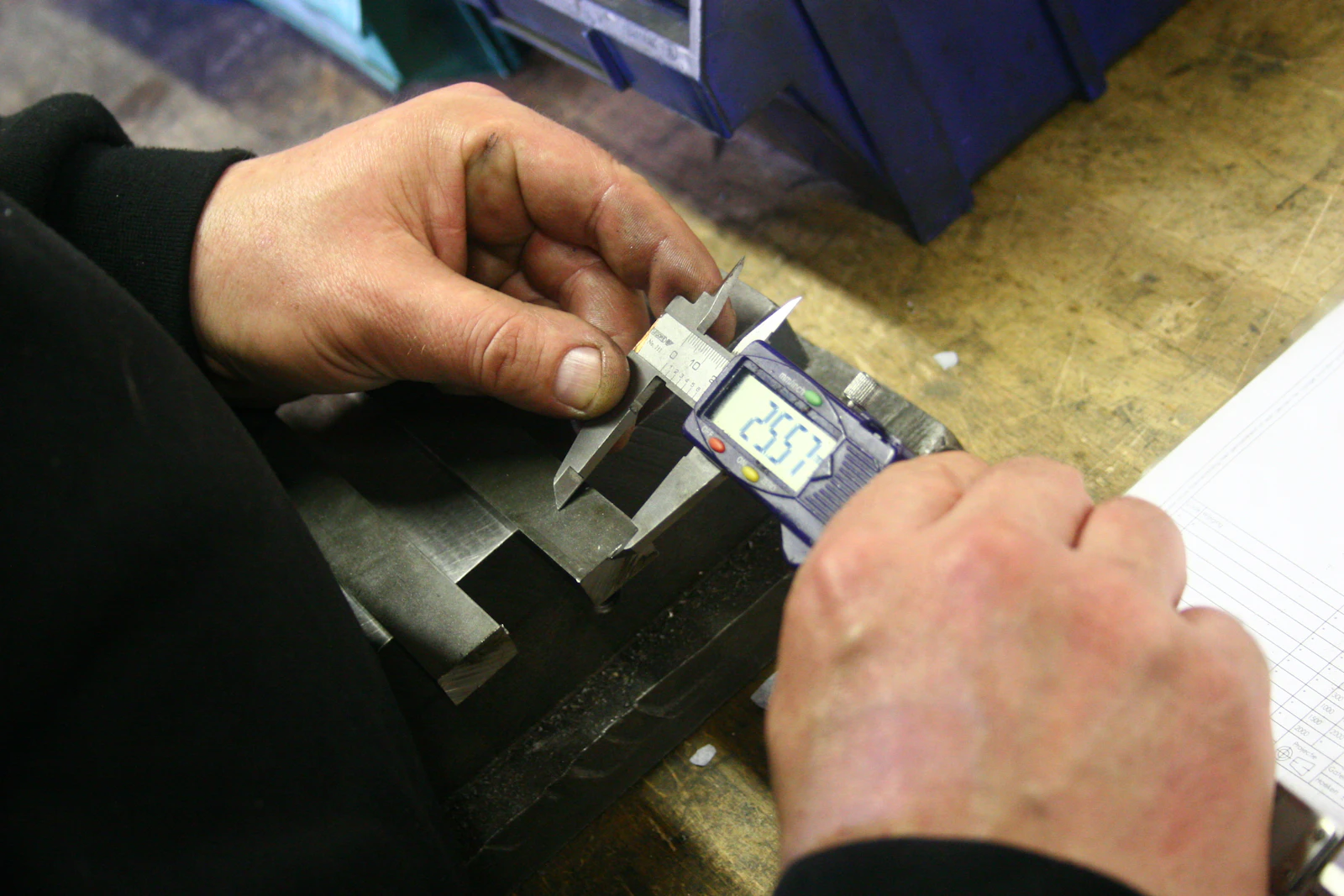
Hands using digital calipers on a metal component.

Manual measurement shown: the automated system must reproduce the agreed quality decision consistently.

ChecksPresence, position, dimension, appearance and assembly
EvidenceResults, counts and selected image records
ResponsePass, reject, alarm, stop or operator review

Direct answer

What is an automated optical inspection system?

A fixed in-line automated optical inspection system uses controlled cameras, lighting and decision software to check visible product features at production speed. It can measure, verify presence or assembly, detect surface or packaging defects and trigger a confirmed pass, reject, alarm or review response.

01 / Engineering focus

Inspection starts with an objective rule

The best systems begin with an observable, measurable difference between an acceptable product and a reject. We define the inspection window, tolerances and decision logic before selecting resolution or software tools.

  • Component presence and correct assembly
  • Position, alignment and orientation checks
  • Dimensional and geometric measurement
  • Surface defect, print, label and packaging inspection
  • Colour, fill level and closure verification
02 / Engineering focus

A reject path that protects the process

Detection only creates value when the affected item is reliably contained and defect escape risk is addressed by the line response. Reject timing, part tracking, full-bin detection, confirmation sensors and fault response are included in the system design.

  • Positive reject confirmation
  • Locked or controlled reject collection where required
  • Fail-safe response to missing confirmation
  • Production totals and reject reason reporting

System sequence

Engineer the complete decision loop.

Every stage is tested against the product, timing, interfaces and agreed response.

01

Define

Agree the defect catalogue, tolerance and decision boundary.

02

Image

Select optics and lighting that reveal the required feature.

03

Prove

Challenge the inspection with representative variation and rejects.

04

Contain

Remove or stop affected product and confirm the response.

Typical applications

Where this capability can fit.

Final suitability and performance are confirmed only after review of the complete production application.

Presence and absence checks
Assembly verification
Dimensional inspection
Surface defect detection
Label and print inspection
Pass/fail data capture

Application questions

What manufacturers ask.

These answers provide a starting point. Product trials and line data determine the project specification.

Can a camera inspect every product at production speed?

Potentially, but exposure time, image transfer, processing time, product spacing and reject response all have to fit within the available cycle. We calculate the complete timing budget rather than considering the camera alone.

Can inspection results be recorded?

Yes. The required result records, counters, timestamps and image-retention policy can be defined around your quality and traceability needs, subject to agreed storage and system interfaces.

Do you need samples of real defects?

Yes wherever possible. Representative acceptable parts, known rejects and natural process variation give a much stronger basis for trials and acceptance than ideal samples alone.

Start with the production task

Show us what the system needs to see and move.

Use the project brief form, or email product photos or video with the target output, current layout and required decision. We will define the next technical step.

Project brief