A specialist website by Oxford Industrial Automation

UK machine vision & robot integration · 01865 416830

Flexible machine loading

Vision-guided robotic machine tending

Locate components that are not held in one precise fixture, orient them for the process and verify the load or unload cycle. Vision, robot, gripper, machine interface and recovery are engineered as one cell.

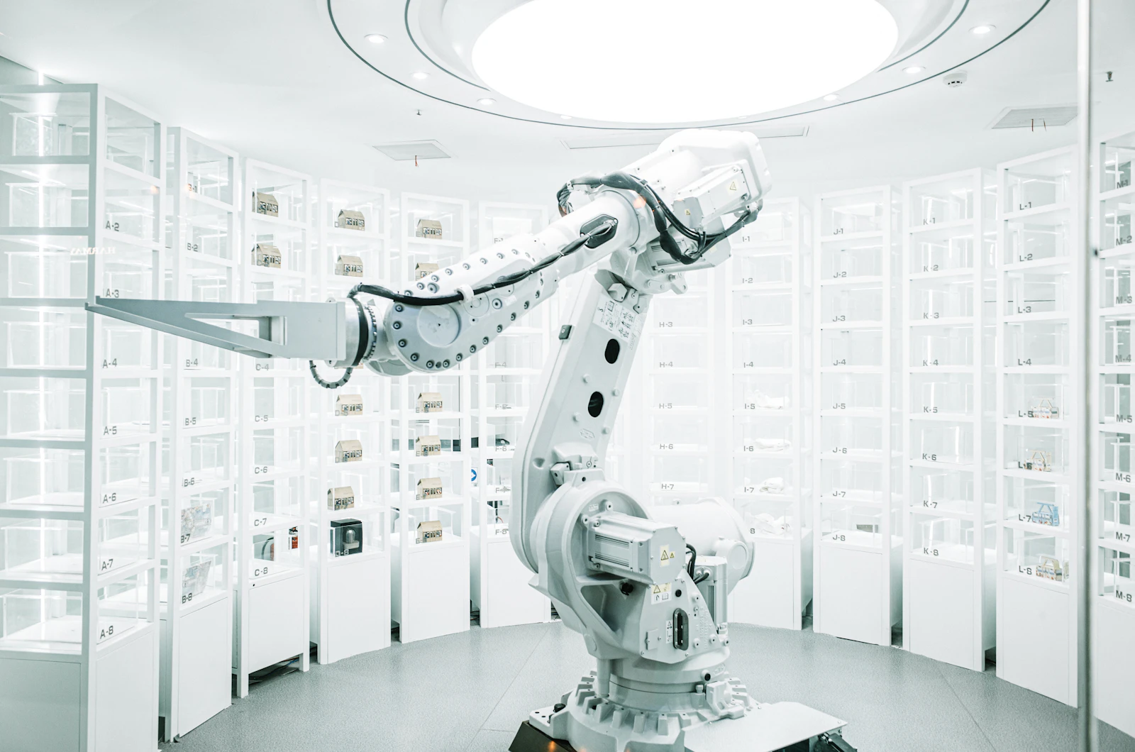
A white industrial robot arm in front of display shelves.
LocateTray, conveyor, pallet, tote or bin presentation
LoadKnown pose for machining, assembly or process equipment
VerifyPart identity, grip, fixture state and cycle result

Direct answer

When does machine tending need machine vision?

Vision becomes useful when part position, orientation or identity varies enough that a robot cannot rely on a fixed nest alone. A camera can locate the next component, provide robot coordinates, verify the correct part and confirm relevant states before loading the machine.

01 / Part presentation

Reduce rigid fixturing without losing control

Parts may arrive in trays, on conveyors, on pallets or in bulk. The presentation method sets the required field of view, depth information, calibration, robot reach and replenishment strategy.

  • 2D location on a controlled plane
  • 3D localisation for height, tilt or random pose
  • Tray, pallet and conveyor coordinate offsets
  • Mixed-part identification where feasible
  • Empty, missing and uncertain-part handling
02 / Machine interface

Coordinate the robot with the production cycle

A reliable cell manages machine-ready signals, doors or access, workholding state, part loading, cycle start, unloading, result routing and safe recovery. The vision result must remain linked to the part through that sequence.

  • PLC and robot handshakes
  • Fixture and chuck state confirmation
  • Grip and part-presence sensing
  • Pass, fail, rework and quarantine routing
  • Changeover, diagnostics and operator recovery

Decision pathway

Locate, load and confirm the complete cycle.

Cycle-time assessment includes product presentation, image processing, robot travel, machine access and recovery—not the robot move alone.

01

Locate

Find the next suitable component and calculate its usable pose.

02

Verify

Confirm identity, orientation and a valid gripping opportunity.

03

Load

Place the component into the process fixture or workholding.

04

Recover

Handle no-part, failed-grip, process-fault and replenishment states.

Application opportunities

Where guided machine tending can fit.

Final suitability depends on part geometry, presentation, cycle time, machine access and the required process interface.

CNC and process machine loading
Moulding and component unloading
Press or assembly feeding
Tray and pallet handling
Bin-to-machine part supply
Inspection before or after processing

Questions manufacturers ask

Machine-tending application questions.

Use these answers to frame the first application review and the evidence needed next.

Can one vision system handle several part variants?

Potentially, if the variants can be identified reliably and the robot, tooling, machine fixtures and recipes support each format. The changeover and wrong-part response must be designed explicitly.

Is 3D vision always required for machine tending?

No. 2D vision may be sufficient for parts lying on a controlled plane. 3D is considered when height, tilt, overlap, bin presentation or full spatial pose affects the pick.

Can vision-guided tending use an existing machine?

Often, subject to safe access, usable machine signals, workholding state, cycle timing, available floor space and the ability to integrate doors, guards and recovery.

What should be tested first?

Representative parts, the most difficult surfaces and presentations, the intended gripper, target pose, machine access and the full timing budget should be reviewed before final specification.

Start with the production evidence

Show us the parts, presentation and machine cycle.

Use the project brief form, or email part images or process video with tray or bin details, machine interfaces and target cycle time.

Project brief